


I’ve written a lot about the many features of Hiperwall’s video wall software to help maintain content integrity and make sure your content is visible when you need it. To do its job, however, the software needs a well-designed hardware platform to make everything work. This article is the first in a series that will present some of the great system architecture designs deployed in Hiperwall systems around the world. Our amazing integrators developed these system architectures, often in consultation with the Hiperwall Technical Services team, to support their customers’ needs in mission-critical environments. Through these articles, it will be clear that deploying video wall systems in control rooms and mission-critical environments requires a deep understanding of customer needs and engineering skills to meet them. I’m so impressed with what our integrators, dealers, and partners all over the world have done, I will present some of their solutions here so we can all learn from them.
What is a Control Room LED Video Wall?
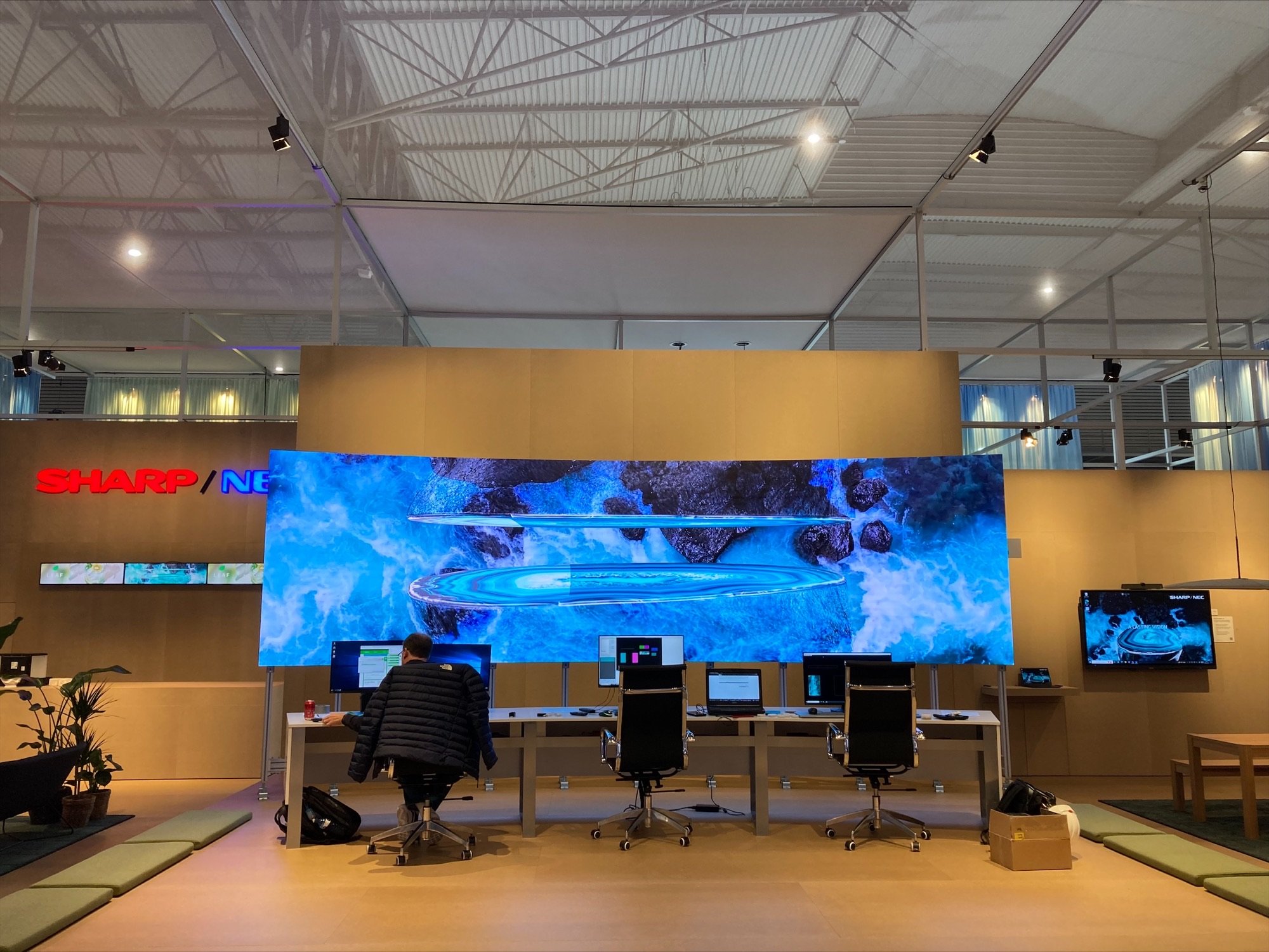
This first article covers LED video wall architectures for control room environments. LED video walls are becoming more popular for control rooms as the prices drop and pixel pitch shrinks. The LED tiles used in control rooms tend to be higher density than those used in signage applications, where resolution isn’t as critical. Control room LED tiles often have a pitch of 1.5mm or better, with 0.9mm readily available These systems have much lower pixel density than video walls made with 55” LCD panels, but they are brighter (which is not always appropriate in dark control rooms) and seamless, which means they look amazing. The tiles are typically either square or 16x9 aspect ratio with a few hundred pixels in each dimension and are installed in arrays that form the video wall with millions of pixels in total.
LED video walls are driven by one or more LED controllers that convert an input signal (1080p via HDMI, for example) into the signals that drive the array of tiles that make up the video wall, often via RJ45 outputs. If the video wall display supports a higher resolution than a single controller can output, multiple LED controllers can be used, each being driven with a different input signal. Because the constructed resolution of the pixels being driven by an LED controller may not match the input signal, the LED controller can either fit the source, squishing it and losing resolution, or crop it, which means some of the source content is not shown. Hiperwall software has a support option for LED cropping to make sure every pixel of your content is displayed properly.
Simple LED Video Wall System Architecture
A simple architecture for an LED video wall system consists of the LED display tiles, an LED controller, and a PC or Player device to drive the content (in Hiperwall’s case, that is the HiperView or HiperView Quantum software running on a PC). For this article, the architecture options will involve the LED controllers and the PC/Player and their connectivity. LED controllers and the LED tiles have their own connectivity options and reliability approaches that are the domain of LED vendors and are beyond the scope of this article.
If either the LED controller or the PC/Player fails, then the wall fails too, which is a problem in mission critical environments. The rest of this article will discuss several options to address this single point of failure issue. Because the expense in LED video walls is mostly in the LED display itself, additional hardware to increase failure tolerance and content integrity adds a very small percentage to the total hardware cost. It takes very little expense to be prepared in case of component failures, but it requires thoughtful design of the system architecture in advance of deployment.
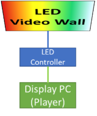
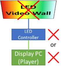
In the simplest configuration, a single failure disables the entire video wall.
Multiple Wall Segments
One of the most capable approaches, particularly for larger LED video walls, is to use multiple LED controllers and multiple PCs/Players, each driving a different segment of the wall, as shown below. This is obvious for larger LED walls because their resolution may be higher than what can be driven by a single LED Controller. Some LED vendors use 4K or even 8K LED controllers, which is fine for digital signage, but bad for control room LED video walls because, if something fails, all or most of the video wall becomes unusable. By splitting the work between LED Controllers and PCs/Players, a failure only takes out a portion of the video wall, so the rest of the wall can be used while the failed component is restored. This approach adds the benefit of splitting the rendering work of the display PCs so more content can be drawn simultaneously on the large LED video wall.
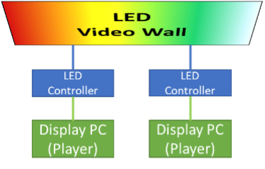
Driving different segments independently means failures are contained.
The downside of this approach is synchronization between the different segments. Hiperwall’s HiperView Quantum uses a hardware-enabled synchronization approach to make video playback seamless even if the video or stream crosses the boundary between segments driven by different PCs. This makes the entire LED video wall a unified canvas for seamless playback of multiple camera streams, capture card feeds, or video files.
This multiple-segment approach is in common use by our control room customers, with one of the largest driving a more than 100-million-pixel LED video wall with tens of LED controllers and tens of HiperView Quantum PCs synchronizing content display across the entire system. If an LED controller fails, only a very small segment of the wall is unusable, while if one of the PCs fails, the loss is just a few percent of the total wall, so content can easily be reconfigured while repairs are performed. The multiple-segment architecture is very capable and flexible and is highly recommended for large LED video walls.
Active Standby
For smaller LED video walls that can be driven by a single PC/Player and just a few LED controllers, having a second PC/Player on active standby is a powerful option. As shown in the figure below, if one of the PCs fails or needs an update, the other one can take over simply by switching inputs on the LED controller(s). Since both PCs are assigned to occupy the same space on the video wall, they draw the same content, thus the video wall continues to work if one is not available. For customers that need the highest reliability and content integrity, this approach can be combined with the multiple-segment architecture, with each segment having an “active standby” PC always ready to be switched in if needed.
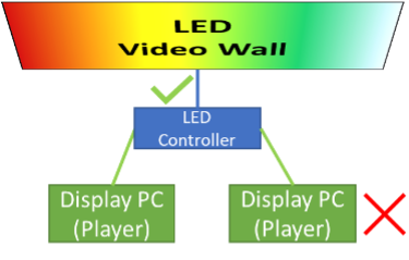
An active standby PC can take over immediately if needed.
Conclusion
Designing an LED video wall for mission critical applications that can continue to operate in the presence of component failures requires engineering evaluation of likely problems and architectural choices to mitigate them. In this article, we have examined splitting the video wall into multiple segments that are driven independently, thus minimizing the impact of failure, and using additional resources in active standby mode to take over in the case of failure. Each of these approaches is in use in Hiperwall LED video walls deployed throughout the world and are proving very effective at maintaining system readiness and availability. The flexibility and capability of the Hiperwall video wall software makes these approaches effective for the reliable display of mission critical information in control rooms.